 English
 Espaol
 Franais
 阿拉伯
阿拉伯 中文
中文 Deutsch
 Italiano
 Português
 日本
日本 韓國
韓國 български
 hrvatski
 esky
esky Dansk
Dansk Nederlands
 suomi
suomi Ελληνικ
 印度
印度 norsk
norsk Polski
 Roman
Roman русский
 Svenska
Perkins珀金斯1506A柴油發動機T400726噴油器供應商,Perkins珀金斯1506A柴油發動機T400726噴油器技術價格規格咨詢服務,Perkins珀金斯1506A柴油發動機T400726噴油器零配件供應,Perkins珀金斯1506A柴油發動機T400726噴油器售后服務中心,Perkins珀金斯1506A柴油發動機T400726噴油器,Perkins珀金斯1506A柴油發動機T400726噴油器詳細的技術參數,

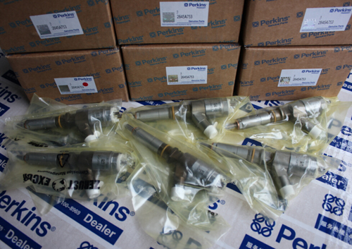
Perkins珀金斯1506A柴油發動機T400726噴油器
詳細描述
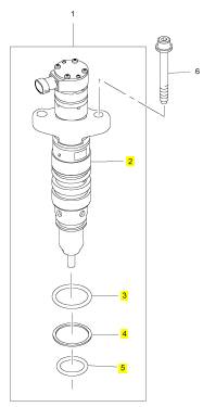
項目 零配件號碼 新件號 描述
1 T400726 6 T400726 噴油器
(1) T400726R 6 T400726R 噴油器 -交換
6 CH11837 12 CH11837 公制的螺拴
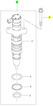
項目 零配件號碼 新件號 描述
2 1 噴油器
3 T400940 2 T400940 密封 -噴油器
4 T400941 1 T400941 圈
5 T400942 1 T400942 密封 -噴油器
|
Peregrine EDi and 1300 Series EDi |
|
Sensor for injection control pressure |
|
The sensor for injection control pressure is of the variable capacitance type, which uses pressure to vary a voltage signal. This sensor sends its voltage signal to the engine control module, at a value between 0 volts and 5 volts. |
|
High-pressure pump |
|
The high-pressure pump has a drive gear, which is driven by the upper idler gear. It is a rotary pump with seven pump elements that have a constant stroke. The flow of oil from the pump will vary with engine speed. |
|
2 A pressure relief valve in the body of the pump opens at 27,6 MPa (4000 lbf/in ), it discharges oil into the timing case. |
|
Regulator valve |
|
The regulator valve is fitted to the high-pressure pump, and consists of a solenoid connected to a valve. |
|
The solenoid receives a signal voltage from the engine control module, the value of the signal affects the amount of valve movement. |
|
2 The valve changes the injection control pressure to a value between 3,5/20,7 MPa (500/3000 lbf/in ). The value is changed by the amount of oil the valve discharges into the timing case. |
|
l To decrease the injection control pressure, the valve discharges more oil into the timing case, this sends less oil to the supply manifold. |
|
l To increase injection control pressure, the valve discharges less oil into the timing case, this sends more oil to the supply manifold. |
|
Supply manifold |
|
The supply manifold supplies oil and fuel to the fuel injector units, through drillings. Engine oil is supplied at |
|
2 |
|
injection control pressure, and fuel is supplied at 413 kPa (60 lbf/in ). |
|
Workshop Manual, TPD 1353E, Issue 3 |
|
151 |
|
This document has been printed from SPI². Not for Resale |
![]()
![]()
|
10 |
|
Peregrine EDi and 1300 Series EDi |
|
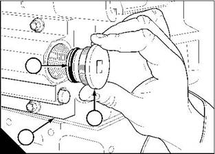
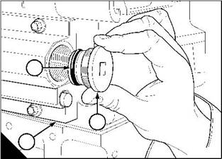
Sensor for injection control pressure |
|
To remove and to fit |
|
Operation 10-20 |
|
To remove |
|
1 Disconnect the electrical cable at the sensor for injection control pressure. 2 Remove the sensor for the supply manifold and discard its ‘O’ ring. |
|
To fit |
|
1 Fit a new ‘O’ ring to the sensor. |
|
2 Apply Loctite 277 to the threads of the sensor. 3 Fit and tighten the sensor to 26 Nm (19 lbf ft) 2,6 kgf m. |
|
152 |
|
Workshop Manual, TPD 1353E, Issue 3 |
|
This document has been printed from SPI². Not for Resale |
![]()
![]()
![]()
![]()
|
10 |
|
Peregrine EDi and 1300 Series EDi |
|
High-pressure pump |
|
To remove |
|
Operation 10-21 |
|
To remove |
|
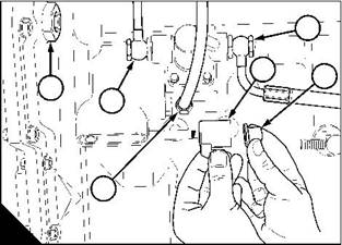
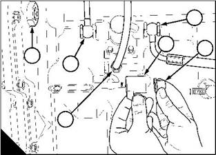
1 Disconnect the electrical cable (A2) at the sensor (A1) for engine oil temperature. |
|
2 Disconnect the electrical cable (A4) at the solenoid (A3) of the regulator valve for injection control pressure. |
|
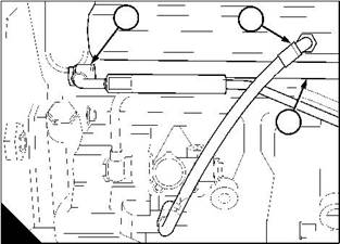
3 Remove the banjo bolts (B2 and B4) from the fuel pipes of the lift pump, remove and discard the copper washers. |
|
4 Disconnect the high-pressure oil pipe (B3). |
|
4 |
|
5 |
|
6 |
|
1 |
|
1 |
|
2 |
|
2 |
|
3 |
|
3 |
|
4 |
|
A |
|
B |
|
W229 |
|
W230 |
|
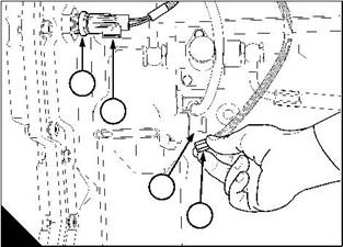
5 Remove the nut (B6) that retains the solenoid (B5). 6 Remove the sensor for engine oil temperature. |
|
7 Use a suitable pump to drain the reservoir for the high-pressure system. Drain the reservoir through the hole for the sensor (B1). |
|
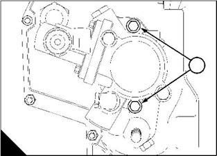
8 Hold the high-pressure pump, remove the two setscrews (C1) that retain the pump. Remove the pump and discard the joint. |
|
1 |
|
C |
|
W232 |
|
Workshop Manual, TPD 1353E, Issue 3 |
|
153 |
|
This document has been printed from SPI². Not for Resale |
![]()
![]()
![]()
![]()

|
10 |
|
Peregrine EDi and 1300 Series EDi |
|
To fit |
|
Operation 10-22 |
|
1 Fit a new joint to the pump. |
|
2 Align the drive gear to mesh with the lower idler gear, push the pump into the rear of the timing case. Fit and tighten the two setscrews (A1) to 27 Nm (20 lbf ft) 4,8 kgf m. |
|
1 |
|
A |
|
W232 |
|
3 Fit the sensor (C1) for engine oil temperature and connect its electrical cable (C2). |
|
4 Fit the solenoid (B5) of the regulator valve. Fit and tighten its nut (B6) to 6 Nm (4.5 lbf ft) 0,6 kgf m. Connect its electrical cable (C4). |
|
5 Connect the fuel pipes to the fuel lift pump, fit new copper washers to the banjo bolts (B2 and B4). Tighten the banjo bolts to 35 Nm (26 lbf ft) 3,6 kgf m. |
|
6 Fit the high-pressure oil pipe (B3). |
|
4 |
|
5 |
|
6 |
|
1 |
|
1 |
|
2 |
|
2 |
|
3 |
|
3 |
|
4 |
|
B |
|
C |
|
W230 |
|
W229 |
|
154 |
|
Workshop Manual, TPD 1353E, Issue 3 |
|
This document has been printed from SPI². Not for Resale |
![]()
![]()
![]()
![]()


|
10 |
|
Peregrine EDi and 1300 Series EDi |
|
Regulator valve for injection control pressure |
|
To remove and to fit |
|
Operation 10-23 |
|
To remove |
|
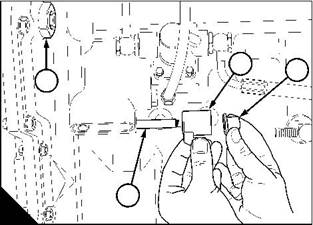
1 Disconnect the electrical cable (A2) at the sensor (A1) for engine oil temperature. |
|
2 Disconnect the electrical cable (A4) at the solenoid (A3) of the regulator valve for injection control pressure. 3 Remove the sensor (A1). |
|
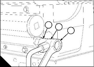
4 Use a suitable pump to drain the reservoir for the high-pressure system. Drain the reservoir through the hole for the sensor (B1). |
|
5 Remove the nut (B3) that retains the solenoid (B2). 6 Remove the regulator valve (B4). |
|
To fit |
|
1 Fit and tighten the regulator valve (B4) to 47 Nm (35 lbf ft) 4,8 kgf m. |
|
2 Fit the solenoid (B2) of the regulator valve. Fit and tighten its nut (B3) to 6 Nm (4.5 lbf ft) 0,6 kgf m. Connect its electrical cable (A4). |
|
3 Fit the sensor (A1) for engine oil temperature and connect its electrical cable (A2). |
|
2 |
|
3 |
|
1 |
|
1 |
|
2 |
|
3 |
|
4 |
|
4 |
|
A |
|
B |
|
W229 |
|
W230/1 |
|
Workshop Manual, TPD 1353E, Issue 3 |
|
155 |
|
This document has been printed from SPI². Not for Resale |
![]()
![]()
![]()
![]()
|
10 |
|
Peregrine EDi and 1300 Series EDi |
|
Supply manifold |
|
To remove |
|
Operation 10-24 |
|
1 Put a container of approximately 2 litres (4 pints) under the drain plug (B2) for the supply manifold. |
|
2 Remove the banjo bolt of the fuel return pipe (A3), and disconnect the banjo union (A2). Discard the copper washers. |
|
3 Remove the valve (A1) for the fuel return pipe. |
|
4 Remove the plug (B2) and drain the lubricating oil from the gallery in the supply manifold (B3). Remove and discard the ‘O’ ring (B1). |
|
1 2 1 3 |
|
2 |
|
3 |
|
A |
|
B |
|
W213 |
|
W212 |
|
5 Remove the container and discard the fluids safely in accordance with local regulations. 6 Disconnect the high-pressure oil pipe (C1) at the supply manifold (C3). |
|
7 Disconnect the fuel pipe (C2) at the supply manifold. Discard the copper washers. |
|
8 Remove the 12 setscrews that retain the supply manifold, remove the manifold. Remove and discard the joint. |
|
2 |
|
1 |
|
3 |
|
C |
|
W211/2 |
|
156 |
|
Workshop Manual, TPD 1353E, Issue 3 |
|
This document has been printed from SPI². Not for Resale |
![]()
![]()
![]()
![]()

|
10 |
|
Peregrine EDi and 1300 Series EDi To fit |
|
Operation 10-25 |
|
1 Fit the supply manifold, together with a new joint. Fit and tighten the setscrews to 27 Nm (20 lbf ft) 2,8 kgf m. Caution: Ensure that the word “FRONT” on the joint is toward the supply manifold. |
|
2 Fit the fuel pipe (A2) at the supply manifold (A3), together with new copper washers. 3 Fit the high-pressure oil pipe (A1). |
|
2 |
|
1 |
|
3 |
|
A |
|
W211/2 |
|
4 Fit the drain plug (B2), together with a new ‘O’ ring (B1). 5 Fit the valve (C1) for the fuel return pipe. |
|
6 Connect the banjo union (C2) of the fuel return pipe, together with new copper washers. Fit and tighten the banjo bolt (C3) to 35 Nm (26 lbf ft) 3,5 kgf m. |
|
7 Eliminate air from the fuel system, see Operation 11-9. |
|
1 |
|
2 |
|
1 |
|
3 |
|
2 |
|
3 |
|
B |
|
C |
|
W212 |
|
W213 |
|
Workshop Manual, TPD 1353E, Issue 3 |
|
157 |
|
This document has been printed from SPI². Not for Resale |
![]()
![]()
![]()
![]()

|
This page is intentionally blank |
|
This document has been printed from SPI². Not for Resale |
|
Peregrine EDi and 1300 Series EDi |
|
11 |
|
Fuel system |
|
11 |
|
General description |
|
Fuel from the tank passes through a pre-filter and a pipe to the fuel strainer (A5). The fuel passes from the strainer, through a passage in the filter head (A4), then through a pipe to the lift pump (A7). From the lift pump fuel passes, under pressure, through a pipe and through the filter head to the filter canister (A6). |
|
Clean fuel leaves the filter canister and returns to the filter head, then passes through a pipe to a gallery in the |
|
2 |
|
supply manifold (A2). A valve (A3) in the supply manifold operates at 414 kPa (60 lb/in ) and allows fuel to |
|
return to the fuel tank, through a pipe. |
|
Fuel from the supply manifold passes through galleries in the cylinder head, to the fuel injector units (A1). The |
|
2 |
|
injector unit increases the pressure of the fuel to 24/124 MPa (3500/18000 lbf/in ), and atomised fuel is injected |
|
into the cylinders. |
|
Cautions: |
|
l It is very important that dirt does not enter the fuel system. Before a connection is disconnected, clean thoroughly the area around the connection. After the component has been disconnected, fit a suitable cover to all open connections. |
|
l The fuel injection equipment must only be checked and adjusted by personnel who have had the correct training. |
|
l The hydraulically actuated, electronically controlled unit injectors (HEUI). There is no repair for these injector units, they can only be renewed. |
|
1 |
|
3 |
|
2 |
|
4 |
|
5 |
|
7 |
|
6 |
|
A |
|
W238 |
|
Workshop Manual, TPD 1353E, Issue 3 |
|
159 |
|
This document has been printed from SPI². Not for Resale |
免費熱線
400-082-9096?
400-082-9096?
整機銷售
0731-84424871? 18374999699
0731-84424871? 18374999699
售后維修
0731-84424872? 15580888444
0731-84424872? 15580888444
配件銷售
0731-84424873? 18274802060
0731-84424873? 18274802060
手機端

微信公眾號